Resources
Overheating
Technical Discussion Page
IMPORTANT SAFETY FACT
The GPz900r has a pressurised cooling system. This means the water/coolant can become super-heated, well above 100°C (212°F), but will not be boiling BECAUSE of the pressure. When you undo a hot radiator cap you instantaneously release the pressure – so super-heated water will immediately boil, turning into super-heated steam with an extremely high potential for serious injury.
Always let a hot engine cool down!
Schematic Diagram & Basic Overview
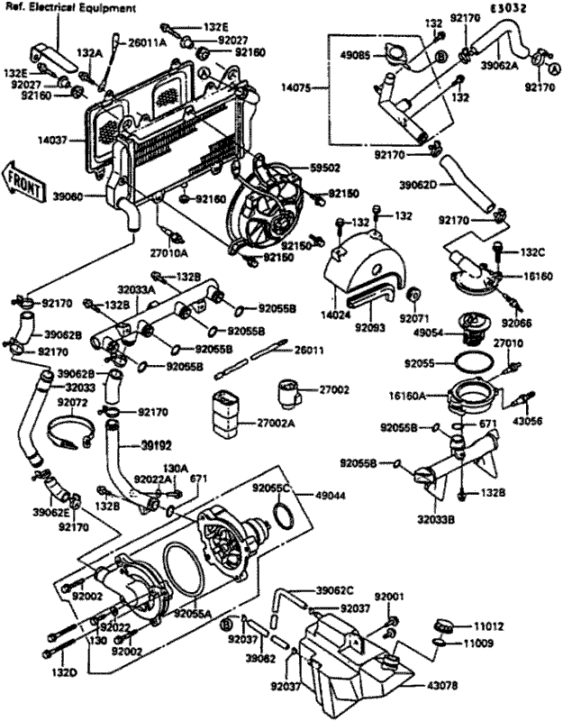
Image from kawasakionlineparts.com.au.
Cooling system for Dummies – my explanation for those who don’t know how it works!
Cooling is not the best description – because we generally think of cooler as being a temperature LESS than something else. So a cooling system makes things colder right? Well, no. The role of the cooling system in an engine is actually to hold the engine at the ideal operating temperature.
Air cooling (used for many older bikes) is far far simpler – no seals, water, components, etc. But water absorbs heat better than air, so water cooled engines can run hotter – which is more efficient. But interestingly all engines are ultimately air cooled! This is because even liquid cooled engines move heat from the engine to water and then from the water to air.
How does it work?
Think of an electric kettle. Yes we think of it as heating the water for a cup of tea, but another way of looking at this is that the water is cooling the hot electric element. This is a fluid heat exchanger – heat is exchanged from the element to the water. One goes down (or stays the same) whilst the other goes up. The larger the water source means the greater ability to absorb heat, so large kettles take longer to boil than small ones!
If we let the kettle boil then water is lost as steam and this immediately reduces the size of the water source, reducing it’s ability to absorb heat. This is the start of a downward spiral until all the water has disappeared. With no fluid for a heat exchange the element will just get hotter & hotter until it destroys itself – hopefully not burning down the house in the process.
Water-cooled engines use exactly the same principle for the first part of their system – the engine is the hot element and water is used to absorb the heat. But that is only half of the engine cooling system, because the water would just get hotter and hotter until it also boils away and the engine destroys itself (like the kettle)
So the engine liquid cooling system has TWO functions – cooling the engine and then cooling the water.
Water runs from bottom pipe of the radiator (30960) to the engine-driven water-pump (49044). The pump creates the water path that circulates through the different parts – connecting them with pipes & hoses and hose clamps.. Water from the pump is pushed to the water pipe (32033A) that splits the single water flow into 4 ports into the front of the engine.
This is the first part of the cooling system – the engine is cooled by transferring heat to the water (heat exchange #1) which then exits from the back of the engine into another water pipe.
From here heated water hits a temperature sensitive valve – the thermostat (49054). The role of this is simply to minimise the time to warm up the engine and if operating properly it has no effect on the normal cooling system processes. With the engine warm and the thermostat open the water flows to the top of the radiator, and then moves through lots of internal channels within the radiator before reaching the bottom. (heat exchange #2).
The radiator is the second part of the cooling system, A basic understanding of how it works is demonstrated by the household fan. When air blows onto your face we feel cool, even though the air is exactly the same temperature. It achieves this by evaporation, so removing heat = feeling cooler. Although a slightly different process, an engine radiator also needs moving air to exchange heat from the water to the air and thus operate effectively.
This water cycle then repeats, and as long as heat exchange #1 is LESS than heat exchange #2 the system the water will not boil and prevent the engine from overheating.
Temperatures above 100°C
Unfortunately the optimum engine operating temperature is typically above boiling point of water – so higher than 100°C or 212°F. Life would be so much simpler if it were lower! So we want the coolant to be at 100°C but not boil……
We achieve this in a couple of ways.
Coolant – we mix other compounds into water (like glycol) to make coolant, which increases the boiling point as high as 109°C. But there is a limt, the coolant still needs to flow easily (viscosity), not be corrosive to the engine nor be unduly poisonous to human beings!
And this still isn’t high enough for the GPz900r system.
Pressure – an interesting real-world observation is that if you boil water on Mt Everest the temperature your cuppa will be just 70°C or 158°F! Still pretty warm considering! As temperature is directly proportional to pressure, the lower boiling point on the mountain is due to lower atmospheric pressure at high altitudes.
And the reverse is true, so if we increase pressure we can increase the boiling point of the coolant.
A closed system would theoretically allow the pressure to build up indefinitely, in reality this would eventually burst through a join or seal. So the system controls this with valves inside the radiator cap.
110°C is normal
With the ignition switched ON the GPz900r radiator fan only switches on when the coolant temperature at the thermostat housing exceeds 110°C! If it cools down below that – then the fan switches off. So the normal operating temperature (NOT) is 110°C by Kawasaki design!
Well we all think the bike was pretty hot!
Different countries measure pressure differently – Japan uses kg/m², I think US uses psi and Europe uses Bar. Bar:kg/m² ratio is 1:1.02 so pretty well the same.
Dr Google searching tells me that a 1.1 bar (~kg/m²) Radiator Cap (increases the boiling point of coolant to around 132°C (271°F). The earlier versions with a 0.9 bar cap would be less. Still that’s not a lot of margin for error in an Australia where maximum summer temperatures can exceed 40°C – average Japanese summer is 29°C!
It’s also an interesting side-effect of global warming – today the average temperature of Tokyo is 1.5°C hotter than it was in 1984.
This all reinforces the performance heritage of the bike.
When on the move the cooling system is perfect, so the radiator size & coolant volume are all, unsurprisingly, designed to be the minimum size (and weight) to perform effectively when moving. So in the cooler climates of Japan I’m sure she’s fine most of the time, where she gets a bit-hot-under-the-collar is when the ambient temperature is hotter and there isn’t the airflow to:
- optimise heat exchange through the radiator and;
- carry radiated heat away from header pipes, exhaust and the engine itself
The electric fan helps, but it clearly doesn’t move air across the full surface of the radiator and all of the heat extracted from the coolant is blown directly down over the header pipes and back around the engine….which then doesn’t help!
Of course all systems lose some efficiency over time. Corrosion or gunk can impede water flow through the radiator and the engine itself, the water pump might lose some efficiency, the thermostat might not fully open impeding water flow, and the engine itself might run a little hotter. So I suspect that in today’s warmer world even a pristine 30-40 year old cooling system could experience over-heating issues in the city. And on the stinking hot days (38°C/100°F) it probably only takes a few red lights before you are into the danger zone. And there isn’t really a solution except perhaps for a bigger or more effective electric fan.
The Conundrum
If you significantly increase the cooling capacity of the system, then the NOT will drop as a result. So whilst the bike might no longer over-heat in city traffic, the engine will not be running at peak efficiency everywhere else
.
Is what I see normal?
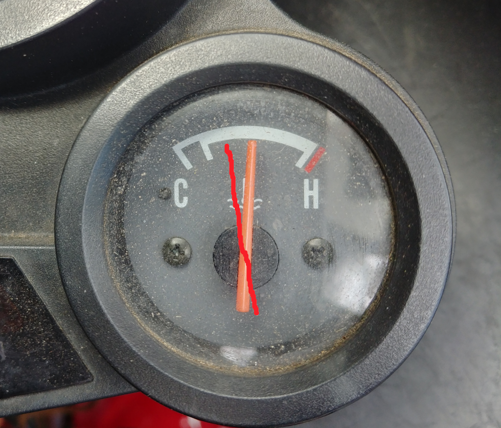
When I’m on the move my temperature gauge now sits steady at 12 o’clock.
But for the previous 5 years I’ve owned the bike the normal gauge position was the red mark. It was only after it all began to go haywire (see temp gauge glitch) and I had to investigate cooling system components that the needle now sits here. Now it could be reasoned that the default gauge position is 12 o’clock and I agree that this is normally true. However my big Ford BA Fairmont temperature gauge sits steady at 1/4, the only time I’ve ever seen it get to 1/2 is a 45°C day in the middle of Australia with the air-conditioning running almost full blast…
My point is unless you buy something new then you won’t know what WAS the original normal.
The complexity with the GPz900r is that all parts of the cooling system could be the cause of over-heating, though it’s more likely a combination of parts. Problems are rarely easy to identify as they can be hidden (eg hose clamps) or just not obvious (e, temp sender wire corrosion)
So IMHO a way to approach over-heating issues is to first confirm the basics – make sure the system is pressurising and there are no leaks from any joins when the system is hot. As I don’t have a pressure gauge the only way is to eye-ball every single join and there are several hidden deep under the fairings and tank.
Fill her with coolant (or even just distilled water for testing) and confirm the water pump is working during the bleed process. How much is normal? Well for my bike at idle (and thermostat closed) nice strong steady stream comes out when you break the bleed nut seal. If it’s only dribbling out with the nut clearly open or surging then I would suspect a faulty waterpump.
Then its fix by replacement. What mean by this is just take a best guess as to which component is faulty and check it is operating at OEM spec. If you can’t check it then I simply replace it. There really aren’t that many components in the system, and even if it doesn’t fix the problem the you know it’s not the fault of this part, and the new part will probably work better than the old one anyway.
If you end up replacing every cooling system component and still have over-heating issues – that sucks. However it likely means that you have bigger problems – which are going to be way more expensive than the cooling system. And when those bigger problems are fixed you have a new cooling system will not only work better but should help prevent the bigger problems from happening again.
Cooling Fan System Explanation
This is a great explanation of the electrics inplay with the cooling system. Because I don’t want this to be lost I have cut and pasted from kawasakimotorcycle.org, please visit forum to read in context.
GPZ 900R COOLING FAN SYSTEM
Send the Missus and kids on a day trip to the Outer Hebrides lock yourself in a room and have an ice-cold beer at your fingertips – you’ll need it! The cooling system on the 900R is fairly complex and cleverly designed, but with a little patience it can be understood to help with those all too common overheating problems – I’m sure that we’ve all had the temperature gauge in the red at some stage, and wondered why the fan hasn’t come on !
The following text hopefully will help you grasp the logic and operation of the system to enable you to tackle any possible faults with gusto and confidence ! Good luck !
The cooling fan circuit consists of three temperature sensors, two relays, and of course the fan. The system automatically provides three modes of operation and to differentiate between them we will consider these as ignition off, ignition on (normal) and ignition on (standby). Whereas each mode utilises different sensors and power supplies, we shall see that the two relays are powered and in use constantly. Let’s now look at the modes of operation:
Ignition off Mode
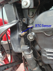
With the ignition off, the first temperature sensor, the 97 C switch (Motoshoot note: on the LH side of the radiator) is armed and if the coolant is at 97 C or above, the fan will be commanded to run until the temperature falls to below 97 C. (Note – this sensor is not active with the ignition on during normal operation.) It is therefore normal for the fan to run when the ignition is turned off with the engine hot.
Ignition on (normal) Mode
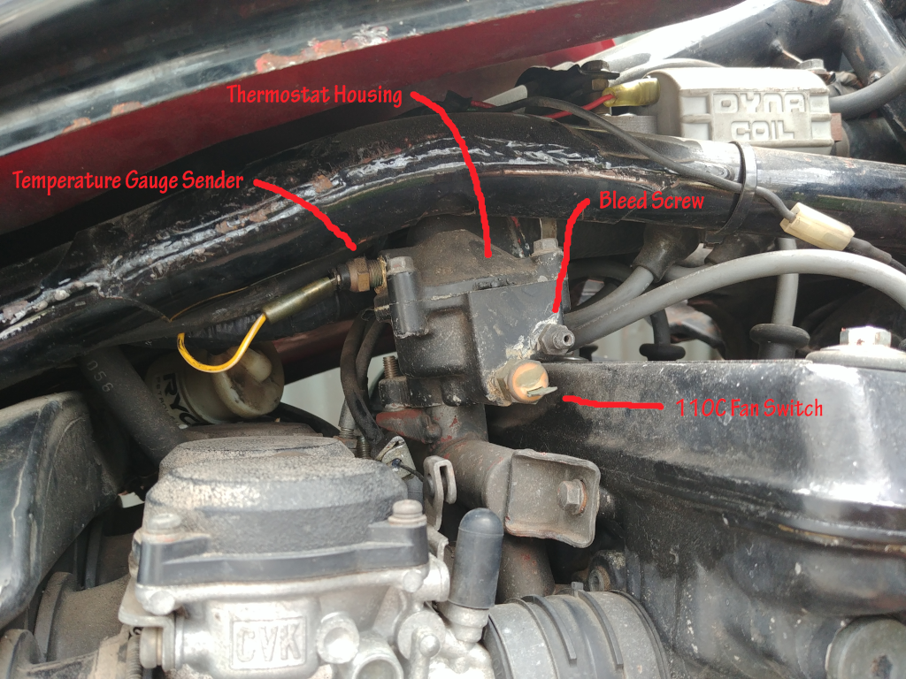
Throughout the ignition on (normal) mode, the 97 C switch is disabled and the second sensor (110C) on the thermostat assembly is armed. This will signal the fan to run if the coolant temperature increases to 110 C. Once the temperature decreases to below this threshold, the fan will cease.
Ignition on (standby) Mode
For the last mode, the third sensor actually measures oil temperature and switches at 120 C. This appears to be a fail-safe feature which switches temperature sensing from the 110 C switch to the 97 C switch if:
1. The 110 C switch is defective (we have to assume that if the oil reaches 120 C, the coolant temperature is above the 110 C threshold, therefore the 110 C sensor has failed).
2. The oil temperature rises due to a problem in the oil cooling system.
Under either of these conditions, the 97 C sensor will be activated to prevent cooking your engine. This will command the fan to run until the coolant temperature decreases to below 97 C.
Relays
The first of the two relays, the Fan Switch Relay is situated adjacent to the headlight and determines which sensor is used under the prevailing operating conditions. It routes an earth signal (if temperature threshold exceeded) from either the 97 C or the 110 C sensor to the Fan Relay (situated adjacent to the fuse box) to bring on the fan. Failure of either of these relays will render your cooling fan system inoperative.
Sensors
Both of the engine coolant temperature sensors function in exactly the same manner, in that the resistance is inversely proportional to temperature – in other words the higher the temperature the lower the resistance. This is in contrast to the oil temperature sensor, which works in the opposite way – the resistance is conversely proportional to temperature, the resistance increases with temperature. The coolant sensors provide an earth when hot, the oil sensor provides an earth when cold.
Remember this – it is invaluable when troubleshooting.
Troubleshooting the system
Before you go tearing the bike apart, first determine if there is a fault – does the fan run when it is supposed to ? If you have read this far you should a fair idea of what is supposed to happen and when. Let us start with a very simple check which does not require fairing removal etc, but it will prove about 90% of the cooling fan system system.
Turn the ignition on, (no need to start the engine) disconnect the black wire from the 110 C sensor on the right-hand side of the thermostat and ground that connector to earth. The fan should run. Refit the wire back on the sensor. Be careful not to snap the terminal off the sensor, they’re delicate!)
If a fault persists, and you suspect component failure, then the place to start is the fuse box, check, the main fuse, the horn fuse, and the fan fuse, each of these has a role to play in the cooling fan circuit.
Remember that overheating can be caused by problems other than component failure, such as, chafed wiring, air locks, sticking thermostat or a particularly bizarre electrical problem.
Two 3ft lengths of wire with crocodile clips at either end is invaluable when troubleshooting, as they enable you to provide power from the battery, to virtually any component on the bike.
COOLING SYSTEM COMPONENT BASIC FAULT-FINDING
Remember that the status of the ignition switch is critical during most of these checks.
To prove the fan. and To Prove the Fan Relay (Situated adjacent to the fuse box)
With the ignition off, disconnect the fan switch relay. (adjacent to the headlight). from the 6 pin connector, earth the Red & White wire. The fan should operate. If it doesn’t the fault lies either in the fan, or the fan relay. Disconnect the two pin connector from the fan, apply 12 Volts directly to the fan. If the fan fails to spin the fan is faulty. If the fan spins, then the fault lies in the Fan relay, or, there is a solitary blue and white wire supplying the fan relay from the rear of the fuse box, this connection often snaps as it is particularly prone to corrosion, remove the fuse box and check this wire.
To prove The Fan Switch relay (Adjacent to the headlight)
With the ignition switched off, disconnect the yellow wire from the 97C switch (rear LH side of the radiator and touch it to earth. The fan should operate. Reconnect the wire.
With the ignition switched on, disconnect the black wire from the 110C switch (side of thermostat housing) and touch it to earth. The fan should operate. Reconnect the wire.
If the fan fails to operate when checking the 97C sensor (yellow wire) it must be assumed that the Fan switch relay is at fault. This can either be replaced, or checked further using the diagnostic checks given in the manual.
If the fan fails to operate when checking the 110C sensor, the fan switch relay, or the oil temperature sensor may be at fault.
To prove the Oil temperature sensor
With the ignition either on or off, disconnect the multiplug connector from the fan switch relay and using an ammeter, check for continuity between the Green & yellow wire, and earth. If there is no continuity, it must be assumed that the oil temperature sensor or the wiring to it is faulty.
To Prove the 97C & 110C sensors
It is a very clumsy process to prove that these sensors are working properly, the procedure for this is featured in all of the manuals. But let common sense prevail. If the system is not working with the ignition on, and you have proven all of the other components by following the above checks then the 110C switch must be at fault. If the fan does not come on when the engine is very hot, and the ignition is off, then the 97C sensor must be faulty.
Nb:- Remember that if the oil temperature sensor is faulty, it will switch the reliance of the cooling system (ignition on) mode from the 110C sensor across to the 97C sensor. In this case the 97C sensor will bring the fan on if the ignition is on, wheras normally it only operates when the ignition is off.
Manual Fan Switch
As described above the electric cooling fan system is complex but very clever. The flaw is that even if the system is working perfectly the the NOT of 110°C means that under hot, low-speed operation the bike may still over-heat because the marginal fan simply kicks in too late.
As such many owners disconnect the sensor and relays and just use a manual switch to turn the fan on or off.
The previous owners(s) had made this modification to my bike and it actually works well. As soon as temps start to climb you just switch on the fan, and this slows the rate of heat increase to get you through slow traffic on most hot days – thought not all.
But there are negatives.
Firstly you have to remember to switch the fan on – and then remember to switch it off. On my bike the switch is placed down in the side fairing and not illuminated, so you often simply forget it is on.
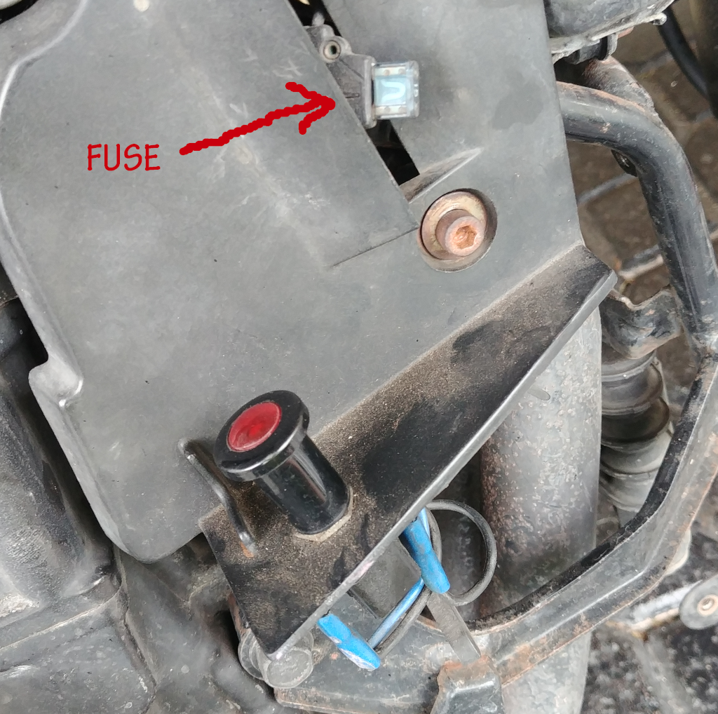
Secondly the new wiring uses an inline fuse that is hidden behind the fairing. If this power is fed from an exiting line (assume it is) then there is another fuse somewhere in the circuit, making fault checking annoying.
Lastly disconnecting the sensors & relays removes any automatic protection in the event of a temperature sender or gauge failure – or just forgetting to switch it on.
I personally think the better solution is to keep the existing OEM system but wire in a second circuit that lets you bypass the entire OEM circuit and force the fan on. The switch should be illuminated and located in easy view (dash surround).
Another electrical option could be to just keep the manual switch as is but still use the sensors to illuminate warning lights.
Radiator Misting


Might need a bike rack to mount the Rapid Cool Radiator Mist Kit!
OK, obviously this product is over-kill, but the concept and logic is sound. The GPz900r only needs additional cooling capacity when stuck in traffic on hot days – so some sort of misting system might actually work!
There is quite a bit of free space in the RH side of the front fairing for a tank and a pump. Of course since it uses water piping it could be mounted anywhere on the bike – or even a backpack. Cheap outdoor misting unit use a 12V pump and are pretty cheap.
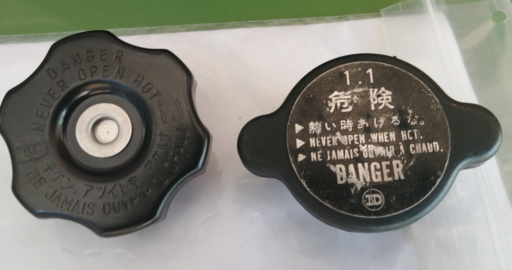
Radiator Caps
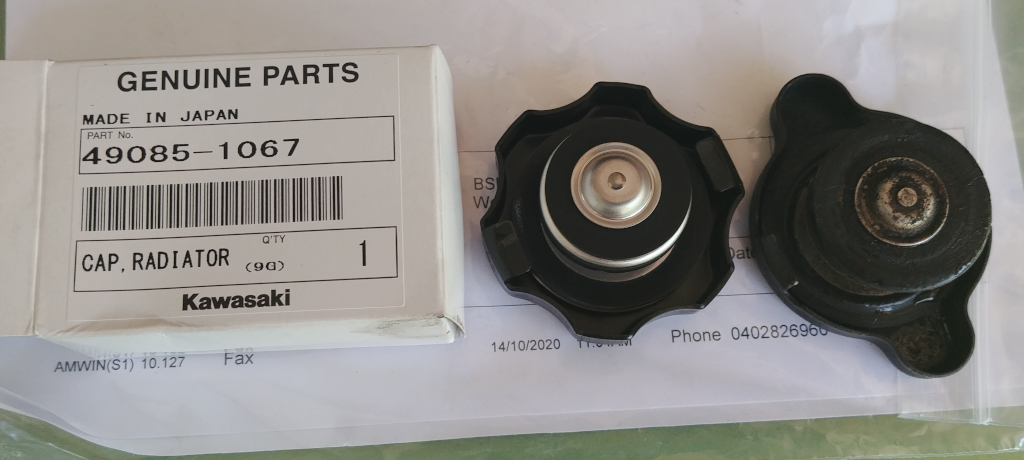
But is a cap worth +AU$60?
As coolant heat rises its volume expands increasing pressure inside the system. At a certain point the valve inside the cap opens allowing coolant to pass through to the overflow tank. As it cools the volume of coolant reduces in the system lowering pressure, so the valve opens again allowing the coolant to flow back from the overflow tank.
So you don’t potentially draw air into the system it’s important to not let the overflow tank get empty!
So yes it’s only a radiator cap, but it’s also a pretty clever dual-action valve. And how much nicer is the original? IMHO just goes to show how more thought went into design in those days – even for this type of functional component!
As discussed the early models had a 0.9kg/cm² cap (see plenty of these on eBay) – later ones 1.1 kg/cm² . Higher pressure gives a higher coolant boiling point, so I would surmise that the higher pressure cap was introduced because the bike was prone to over-heating in traffic. As it is the same cooling system components across all models Kawasaki obviously considered it fine to run the slightly higher pressure for the later versions, so even if I owned an early bike I’d probably replace with the 1.1.
As we know every little bit helps.
New original Nippon Denso caps are no longer available, here is the replacement – used on many Kawasaki’s. A notable difference is the smaller diameter of the rubber pressure seal. I wondered about this but it seems to work OK, and because the seal isn’t contacting the sides of the pipe it’s actually easier to install & remove. Being a modern cheap-skate world the seal thickness is also thinner, hopefully it’s better quality.
FYI the original information is actually printed onto thin aluminium plate – so thin it looks like a sticker. If you use a knife and carefully work it under from the edges you can gently remove the plate – I then just double-sided taped it onto the new one!
Thermostat
Nice article from japan.webike.net discussing the role of a thermostat with images from the GPz900r. I wish it was simple to replace but it isn’t, you really do need to remove the tank first. 🙂
GPz1000RX (ZX1000-A) Radiator & Fan


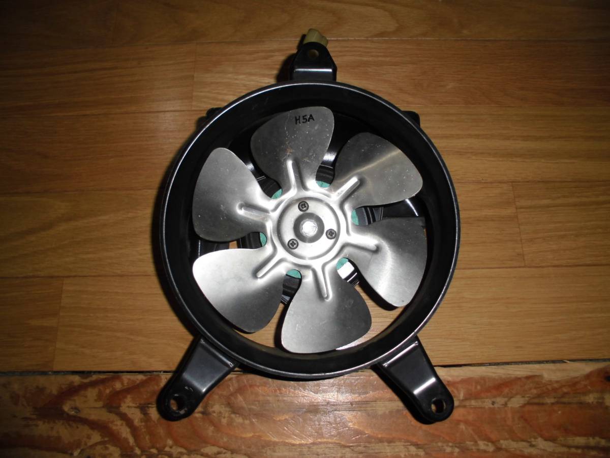
Here are some interesting comparisons with the radiators from the GPz900r and the GPZ100RX – in Australia released as the ZX1000A. As you can see it got significantly bigger, and I have also found a 7-blade fan that apparently is also for the RX – although the shroud/cover doesn’ look right.
I have read that you can fit this radiator into a GPz900r, but you can see that the supporting frame would not allow for the higher RX radiator without modification. The 4-1 headers would also mean that the radiator would need to be positioned differently, but I don’t know if this is the clearance of the standard pipes.
But what is really interesting is the larger fan.
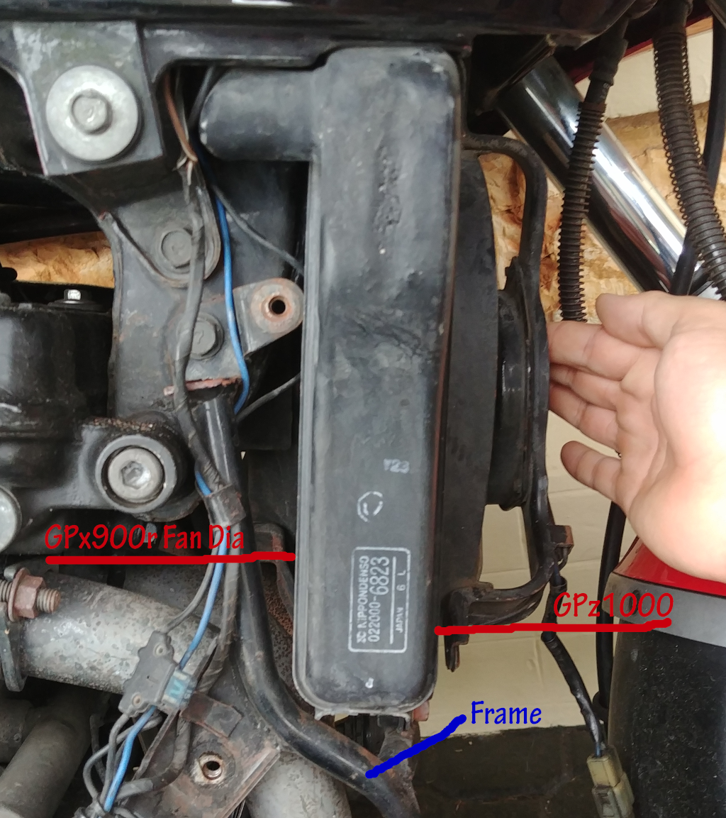
This fan is significantly larger, which means significantly greater area as well as blade tip speed, so potentially this fan moves a lot more air across the radiator. This might be all I need to sort city traffic issues. I have a new aluminum radiator on order from China, so when this arrives I will try and work out how to get it all to fit (it’s not a direct replacement).
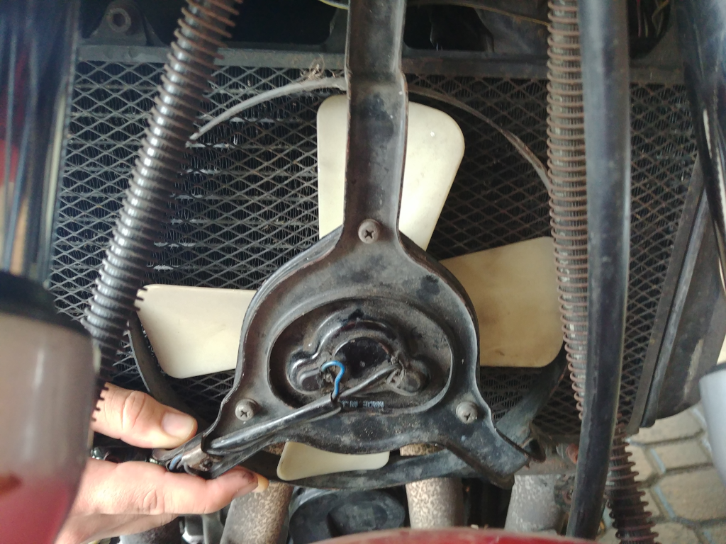
The images below also show the shrouded 7-blade GPz900r fan – I note mine is definitely 4 blades. The 6-blade is an aluminum fan – which was a previously available aftermarket option, but I haven’t been able to source a current supplier. Theoretically less movement in the AL blades means better efficiency, but of course it also means more damage to the radiator if they accidently meet!


Although the RX radiator doesn’t fit it’s not an entirely wasted expense – as when the time comes to rebuild/replace the engine it will have a larger cubic capacity (which means slightly thinner cylinder walls) and maybe even bigger carbs – so I may need to modify the frame to allow a bigger radiator anyway.
Airflow
What is curious is that the OEM fan fro the GPz900r has a close fitting shroud, the GPz1000RX a looser cover panel.
I wonder if the shroud/cover is to prevent rain/water from moving over the top of the engine?
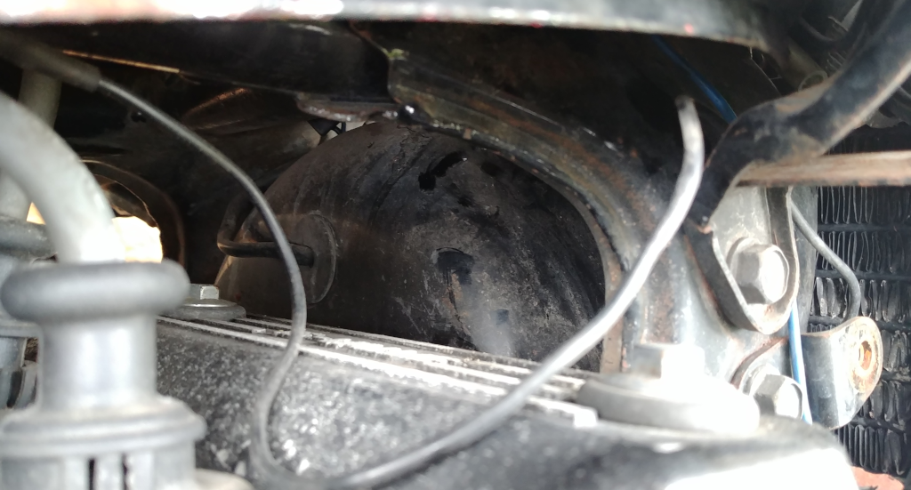
This kinda makes sense, but the shroud/covers aren’t full width nor is there any protection above the radiator anyway, so water will still always move through this zone to the top of the engine. There’s no question that any shroud or cover will reduce the efficiency of the blades, and the photo showing the clearance at the top of the engine would also allow much greater airflow and heat extraction.
It also got me wondering about the side panels. Whilst I appreciate the visual design they are mostly covedred by the main fairing, and I’m not sure that they have any aerodynamic benefit. Being such a tight fit hey would certainly prevent hot air from exiting easily out of the sides of the engine.
So maybe when sitting still the bike will run cooler with the fan shroud and side panels removed? As always every little bit helps!
Coolant
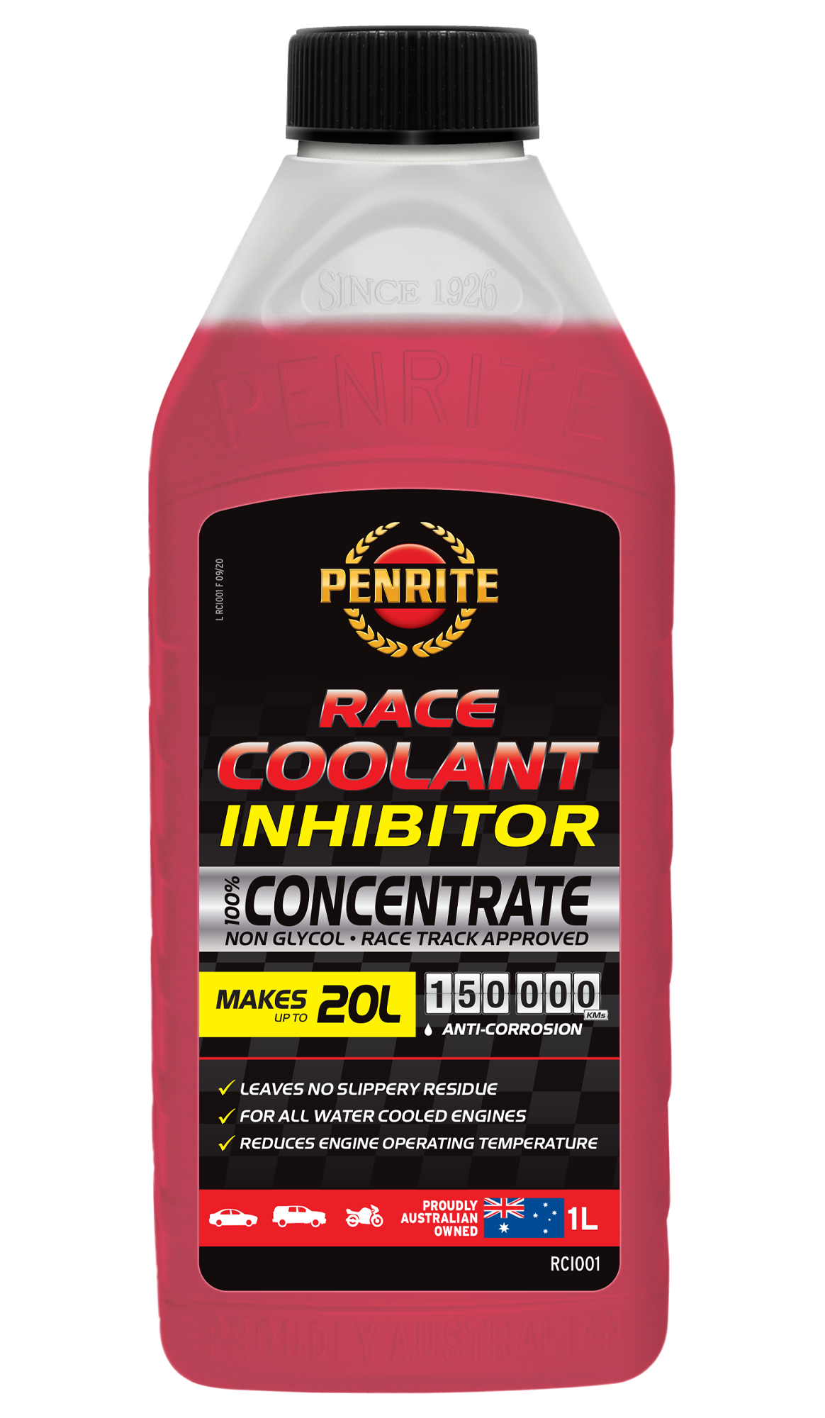
I’m loathe to recommend particular products – but I have just started to use this Penrite product after years of using quality glycol (min 33% concentration) based coolant (green).
IMHO the most relevant factor is that this red product does not have the slipperiness of glycol products – it feels pretty well the same consistency & viscosity as the base distilled water. The idea here is that lower viscosity coolant is not only more efficient (it’s still a Type B anti-boil product), but in the event of a cooling system failure a wet track is still preferable to a slippery one.
GPz900r (ZX900) Database
A1 to A4
A5 to A8
A9 to A12
A13 to A16
About the Site
My family loves older vehicles, the newest one we own is 2003! But I am acutely aware of the ownership complexities especially:
- they often need more 'hands-on' mechanical work &;
- there often isn't any local expertise from the service centres;
- there is often no new parts available from the manufacturer;
- parts often have to be sourced 2nd-hand or from overseas.
So we often end up doing a lot of the research & work ourselves and this information gets stored either locally with the bike or online forums - although finding the useful parts in these forums isn't always simple.
The original goal of the site was simply somewhere for me to record service work & contacts on my GPz900r so that my kids (the one that likes bikes anyway!) could easily access it - it doesn't concern me if it was publicly available.
I then realised that with this online structure in place I could also offer it to other owners, and the site could potentially expand to record other owners experiences and expertise , meaning we can learn from others but also pass on this knowledge to subsequent owners of these wonderful motorcycles.
At least Covid-19 has given me plenty of spare time to pursue my passion for the motorcycle!

Location
Adelaide
South Australia
gpz900r@motoshoot.com.au
Timeline
1983 - Honda XR200
1984 - wanted a GPz
1985-2013 - cars+family
2014 - finally got one!
Disclaimer
The information provided on this site (or links) is personal experiences from non-professional home-mechanics, so neither it's accuracy nor it's validity can be confirmed. If you need professional advise please visit your local Kawasaki dealership or a qualified industry professional.
Like riding any motorcycle, at the end of the day the only opinion that really counts is your own!